In this blog post we look more close to DSP multirate hardware implementation of main four blocks.
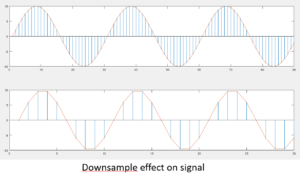
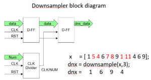
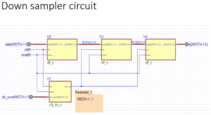
1] Downsample Block downsample(x,n)
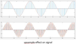
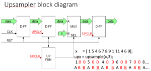
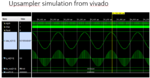
2] Upsample Block upsample(x,n)
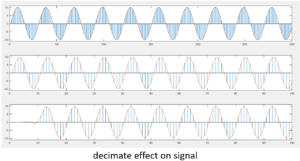
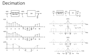
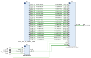
3] Decimation Block decimate(x,n) [ filter + downsample ]
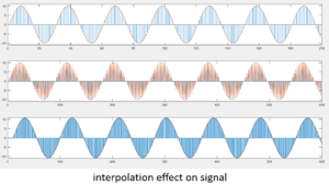
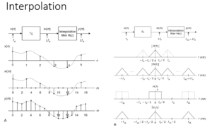
4] Interpolation Block interp(x,n) [ upsample + filter ]
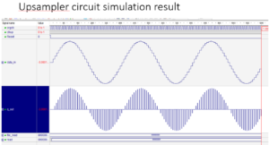
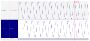
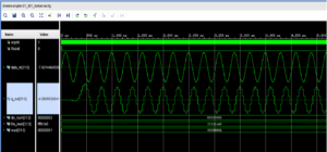
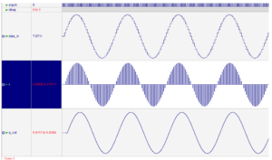
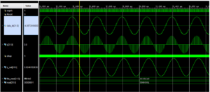
For just view I placed some images for how input and output looks for these blocks to get the functionality.
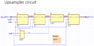
Basic units needed for implementation of multirate blocks are as
1] D flip-flops
2] mux
3] clock divider {int divider, like div by 2,3,..}
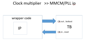
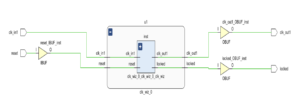
4] clock multiplier , PLL / MMCM IP can be used for this
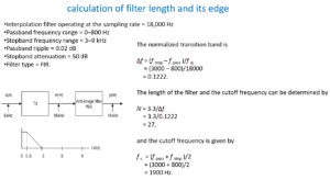
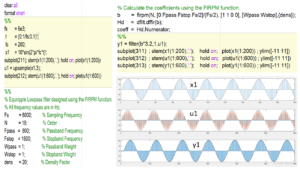
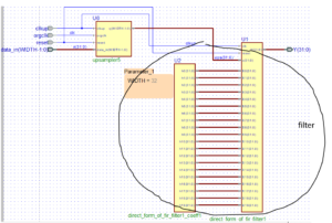
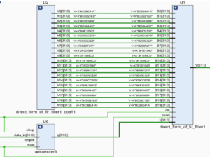
5] filter , here we are using 19-20 tap fir filter
6] for clock controlling fsm may be required
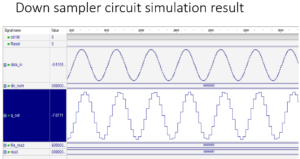
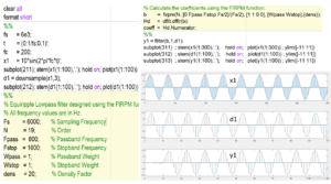
For testing we need signal as well , will generate from matlab
%% signal generation and convert to 32 bit hex format
clc ; clear all
%%
fs = 6e3; % sampling frequency
t = (0:1/fs:0.2)’;
fc = 200; % signal frequency
x1 = 10*sin(2*pi*fc*t)’; % signal
%%
t=[]; % all sample values in variable t (hex 32 bit)
for pnt=1:size(x1,2)
t1 = [ float2bin(x1(pnt)) ];
t = [t;t1];
end
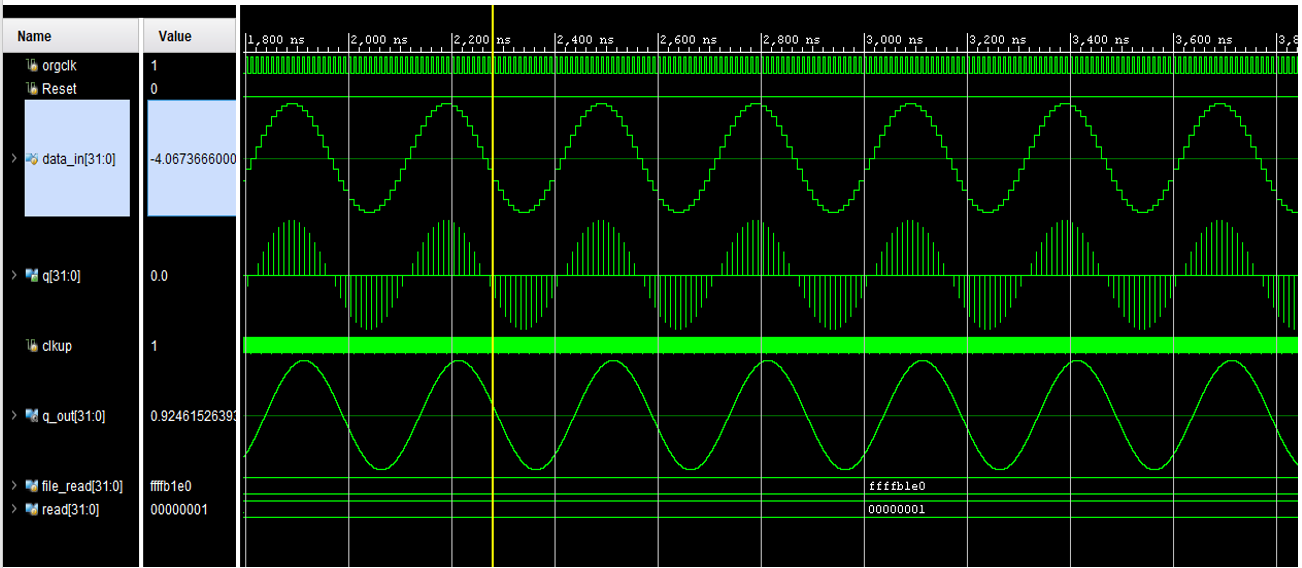
Module test verilog code
`timescale 1ns / 1ps
module test_signal2();
reg clk,reset;
reg [31:0] datax;
//dut instantiation
initial clk = 1’b1;
always #5 clk = ~clk;
initial begin
reset = 1’b1;
#20 reset = 1’b0;
end
integer file_read,read;
initial
begin
file_read = $fopen(“allcnvfiles.txt”,”r”);
End
initial
begin
while (!$feof(file_read))
begin
@(posedge clk);
read <= $fscanf(file_read,”%x\n”,datax);
end
@(posedge clk);
$fclose(file_read);
end
endmodule
Data generator vhdl code, here the array is created and values are taken from the conversion.
entity datagen3 is
port ( clk : in std_logic;
rst : in std_logic;
x : out std_logic_vector(31 downto 0)
);
end datagen3;
architecture Behavioral of datagen3 is
constant N: integer := 1201; —
type arr is array (1 to N) of std_logic_vector(31 downto 0);
constant sd : arr :=
(
x”00000000″,
x”40051040″,
x”408227de”,
.
.
x”2a51b191“ );
begin
— code start
input: process (clk, rst)
variable i : integer := 1; — i = 0 ;
begin
if (rst = ‘1’) then
x <= (others => ‘0’);
i := 1;
elsif (clk’event and clk = ‘1’) AND (i<N) then
x <= sd(i);
i := i +1;
end if;
end process;
end ;
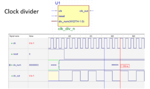
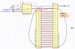
Clock divider module
module clk_div_n #(parameter WIDTH = 32) (clk,reset,div_num, clk_out);
input clk, reset;
input [WIDTH-1:0] div_num;
output clk_out;
reg [WIDTH-1:0] pos_count, neg_count;
wire [WIDTH-1:0] r_nxt;
always @(posedge clk)
if (reset)
pos_count <=0;
else if (pos_count ==div_num-1) pos_count <= 0;
else pos_count<= pos_count +1;
always @(negedge clk)
if (reset)
neg_count <=0;
else if (neg_count ==div_num-1) neg_count <= 0;
else neg_count<= neg_count +1;
assign clk_out = ((pos_count > (div_num>>1)) | (neg_count > (div_num>>1)));
endmodule
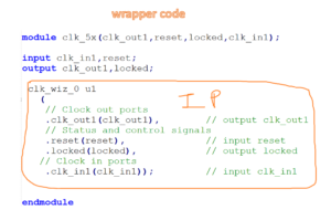
For clock multiplier, PLL/MMCM can be use from xilinx details are given below.


For any help or code you can leave a comment or pm yourstm12@gmail.com